Description
ECE 418: Macromodeling of Analog Circuits was a 3-credit course taught at Michigan State University for Electrical and Computer Engineering majors. The catalog description for this course is: Macromodel methodolgy. Behavior macromodels. Parametric analysis. Op-amp macromodels. Comparator macromodels Voltage regulator macromodels. The co-requisite for this course is ECE 402.
The companion textbooks used in this course are :
Connelly & Choi, Macromodeling with SPICE, Prentice Hall, 1992
M. Rashid, Intro. To PSpice Using Orcad for Circuits and Electronics, Pearson Prentice Hall, 2004
Table of Contents
Chapter 1: Introduction to SPICE
Review of the Sspice Manual
Chapter 2: Macromodeling Methodology
2.1 Arithmetic Functions
Polynomial VCVS, Voltage Addition and Subtraction, Voltage Multiplication, Expression VCVS, LaPlace VCVS, Other Controlled Sources
2.2 Piecewise Linear (PWL) Approximations
Table VCVS, Table VCCS, Simulated Resistance, V-I Characteristics, Frequency Table VCCS, Time Domain Response, Non-Causal Response
Chapter 3: Behavior Macromodels
3.1 An Ideal Op-Amp
Inverting Amplifier, Subcircuit Modeling
3.2 Op-Amp Bandwidth, Input Resistance and Output Resistance
3.3 Ideal Comparator
Noninverting Crossing Detector, Inverting Crossing Detector, Comparator with Hysteresis (Noninverting)
3.4 Multiplier
Basic Multiplier, Balanced Modulator, Amplitude Modualtor, Frequency Doubler, Square Root, Divider, RMS-to-DC Converter
Chapter 4: PSpice as a Tool
A. Parametric Analysis
.PARAM, .STEP, Variable Resistor
B. Goal Functions
Measuring Rise-Time, SEARCH, Measuring Fall-Time, Measuring Bandwidth, General Rise-Time and Overshoot, Peak Detection, Phase Margin
C. Schematic Capture
Voltage Divider, Getting a Resistor, Getting a Voltage Source, Wiring of Components, Labeling the Nodes, Changing Component Values, Placing Text on the Screen, Running the Simulation
D. Parametric Analysis
Fixed-Bias Circuit, Self-Bias Circuit, Fixed-Plus Self-Bias Circuit
E Library Models
Noninverting Amplifier using a UA741 Macromodel
Chapter 5: SPICE Components
A. SPICE as a Tool
SPICE Components; Diodes; V-I Characteristics; Reverse Recovery; NPN BJT; V-I Characteristics; PNP BJT; V-I Characteristics; N-Channel JFET; V-I Characteristics; P-Channel JFET; V-I Characteristics; N-Channel MOSFET; V-I Characteristics; P-Channel MOSFET; V-I Characteristics
Chapter 6: Op Amp Macromodeling
A. Boyle Model
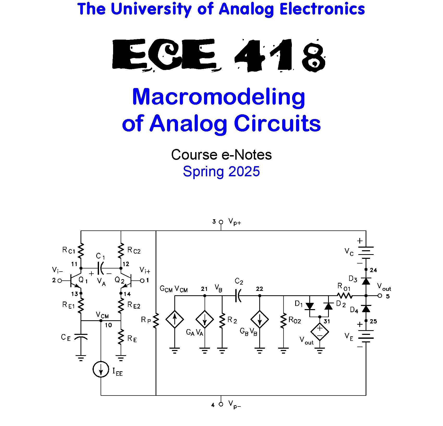
SPICE Test Circuits; Transfer characteristics; Input Bias and Offset Currents; Open Loop Gain; Output Impedance; Common-Mode Gain; Short Circuit Current; Slew Rate; Model Formulas; Input Stage: IC and CE ; SR+; SR-; Jump; Transistor Parameters; Bartlett’s Bisection Theorem; One Capacitor Circuits; Input Stage: RCi and REi ; Input Stage: C1 ; Interstage: GCM ; Output Stage: RO1 , RO2 and GB ; Output: Current Limiting; Output: Voltage Limiting; DC Power Drain; Verification;
Design Procedure; Given Op-Amp Parameters, Pick Component Values; Other Input Stages; PNP Boyle Model; Transfer Characteristics; Slew Rate; Verification; Design Procedure; N-JFET Boyle Model; Transfer Characteristics; Input Stage Changes; Verification; Design Procedure; P-JFET Boyle Model; Transfer Characteristics; Slew Rate; Verification; Design Procedure; Model Inaccuracies; Device Level Model; Supply Current: Device Level Model; Supply Current: Boyle Model; Supply Current: Device Level Model; Supply Current: Boyle Model; Asymmetric Supplies: Device Level Model; Asymmetric Supplies: Boyle; PSRR: Device Level Model; PSRR: Boyle Model; PSrr+: Device Level Model; PSrr+: Boyle Model; PSrr-: Device Level Model; PSrr-: Boyle Model; Supplies Off: Device Level Model; Supplies Off: Boyle Model; Power Up and Down: Device; Output Impedance: Device; Common-Mode Gain: Device
B. MicroSim Model
SPICE Test Circuits; Transfer characteristics; Input Bias and Offset Currents; Open Loop Gain; Output Impedance; Common-Mode Gain; Short Circuit Current; Slew Rate; Supply Current; Supply Current During Clipping; Asymmetric Supplies; PSRR; PSrr+; PSrr-; Supplies Off; Power Up and Down; Model Formulas; Interstage; Input Offset Voltage; Output: Current Limiting; Output: Voltage Limiting; Verification; Design Procedure; Given Op-Amp Parameters, Pick Component Values; Other Input Stages; PNP MicroSim Model; Asymmetric Supplies; Verification; Design Procedure; P-JFET MicroSim Model; “Parts” JFET Macromodels; Verification; Design Procedure; N-JFET MicroSim Model; Verification; Design Procedure; Model Inaccuracies; Asymmetric Supply: Device; Asymmetric Supply: Boyle; Asymmetric Supply: MicroSim; EGND Removed
Chapter 7: Comparator Macromodeling
A. Getreu Model
SPICE Test Circuits; Transfer characteristics; Response Time: 2 mV OD HL; Response Time: 5 mV OD HL; Response Time: 20 mV OD HL; Response Time: 2 mV OD LH; Response Time: 5 mV OD LH; Response Time: 20 mV OD LH; Strobing; Model Formulas; Input Stage: High-to-Low; Interstage: High-to-Low; Output Stage; Input Stage: Low-to-High; Interstage: Low-to-High; Input Stage; Verification; Design Procedure; Given Comparator Parameters, Pick Component Values; Other Output Stages; PNP Getreu Model; Verification; Design Procedure; P-JFET Getreu Model; Verification; Design Procedure
Chapter 8: LM117HV Macromodel Development
I. Development of Macromodels
Functional Block Diagram
II. Macromodeling the AC Specifications
First Pass Model, Ripple Rejection, Symbolic SPICE®, Output Impedance, Open Loop Gain, Lab Testing
III. Macromodeling the DC Specifications
Dropout Voltage, Short Circuit Current Limiter, Foldback Current, Lab Testing
IV. Macromodeling of the Power-Up Transient Response
Room Temperature Macromodel with No Thermal Protection
V. SPICE and Lab Testing of the Macromodel
Current Limiting vs Input Voltage, Dropout Voltage vs Load Current, Ripple Rejection vs Frequency, Output Impedance Magnitude vs Frequency, Power-Up Transient Response, Load Transient Response
VI. Conclusions
